Introducing xTool S1's Pin-point Positioning™
In This Article
- What is Positioning in Laser Operations?
- xTool S1 Pin-point Positioning™
- Introduction to Positioning Methods on the Market
- Advantages and Disadvantages of Absolute Coordinate Method
- Advantages and Disadvantages of Relative Coordinates
- Advantages and Disadvantages of Camera Positioning
- Advantages of Pin-point Positioning™ over Known Positioning Methods
What is Positioning in Laser Operations?
For laser engraving and cutting operations it is important to ensure that the physical location of the object to be engraved or cut matches the exact location represented in the user software.
Generally speaking, we call the action of adjusting the user's expected location relationship as positioning.
For some more complex positioning methods, more software calculations can be involved, in order to get the best and most accurate results, calibration, tolerance control, and mapping needs to be factored in. Especially as it relates to different types of positioning implementations.
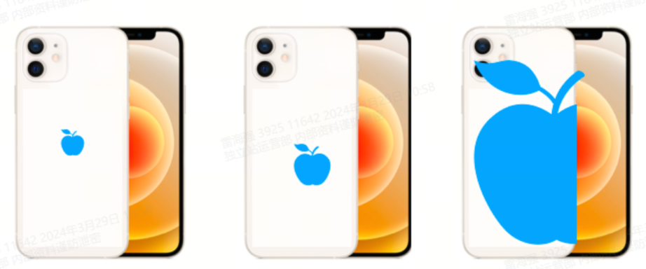
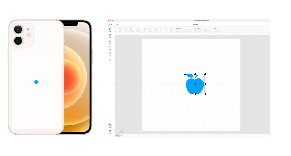
Taking the engraving of an Apple logo on a mobile phone as an example, the typical results of three positioning failures are shown below.
xTool S1 Pin-point Positioning™
The xTool S1 utilizes the positioning method that is the latest and most accurate among all desktop laser machines on the market. Using it is comparable or even more accurate than using a camera.
Pin-point Positioning™, as we name the patented positioning method on xTool S1, provides real time positioning data relative to the X and Y coordinates of the actual laser head movements which are then represented precisely in the software screen.
The core principle of Pin-point Positioning is to use high-precision chips and advanced algorithms to realize the real-time visualization of the change of the laser head position in the machine in software, forming a precise full-scene layout like the XY coordinate system.
This allows users to obtain the position of the processed object by using the cross light spot of the laser head in the real world; and in the virtual world, they can use the visualized light spot position in the software as a reference to quickly and accurately adjust the processing task coordinates and size, so that users can finally obtain the cutting result with the position and size meeting the expectation on the processed object.
Try Pin-point Positioning™ on xTool S1
- Step 1: Move the laser head to the first positioning point
- Step 2: Press the switch to confirm the positioning point
- Step 3: Move the laser head to the second positioning point
- Step 4: Press the switch to confirm the positioning point
- Step 5: The software forms a preview of the positioning area
- Step 6: Drag and drop the pattern into the positioning area
Then you're done with positioning and can operate the next precise engraving.
Highlighted Features
1. Super accurate. Using a coordinate based system is considerably more accurate than manual positioning (error) and camera positioning (distortion);
2. Adapts to more shapes and good at processing leftover material. High accuracy in object centering is realized as a result.
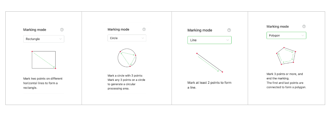
- a. Twin-points Positioning - handling tiny objects
- b. Circular Positioning- locate a circle
- c. Polygonal positioning - special irregular-shape marvels
3. Batch processing. No mold assistance is required, it is more efficient, and items of different shapes can be processed at one time.
Introduction to Positioning Methods on the Market
Laser machines on the market use a variety of specific methods to achieve positioning. It includes "absolute coordinate method", "relative coordinate method", "visual mapping method" and S1's unique "Pin-point Positioning™".
| Specific methods and applications | "Absolute coordinate method" (Open machine without cameras) | "Relative coordinate method" (Open machine without cameras) | Single camera positioning | Dual HD camera positioning (xTool P2) | “Pin-point Positioning™” (xTool S1) |
|---|---|---|---|---|---|
| Basic principle | Pure mechanical focus | Pure mechanical focus | By taking pictures with a single camera, the image of the whole processing area is acquired, and then the algorithm makes the image mapped with the processing area to achieve the effect that the processing image is processed at the place where it is placed. | Through the wide-angle camera to take pictures, the image of the whole processing area is acquired, and then the algorithm makes the image mapped with the processing area to achieve the effect that the processing image is processed at the place where it is placed. And then through the telephoto camera to shoot the local processing area, so that the alignment accuracy is once again improved. | By means of chip motors and algorithms, it combines both physical contact and precise mechanics with the high accuracy and flexibility of the visual mapping-like method presented in the software interface. |
| Positioning errors | 0.01mm, but no preview, hard to locate | 0.01mm, but no preview, hard to locate | 3mm | 0.3mm(xTool P2) | 0.02mm(xTool S1) |
| Step 0 | *Measure the dimensions of items to be processed to determine the appropriate size for the task. | ||||
| Step 1 | Based on prior calibration methods, the base plate has a coordinate scale that is consistent and corresponds to the canvas coordinates of the host computer software. | Place the object to be processed anywhere on the bed | Cameras and other means are used to reconstruct the image of the object to be processed relative to the bed, which contains the positional relationship of each point of the object to be processed and clearly presents the dimensional information of the surface to be processed. | The camera and other means are used to reconstruct an image of the object to be machined in relation to the sub-bed, which contains the position of the various points of the object to be machined in relation to the sub-bed, and thus also clearly presents the dimensional information of the surface to be machined. | Place the object to be processed anywhere on the bed |
| step 2 | Use the scale to know the position coordinates of the object to be processed after it is placed. | Move the laser head to a specific position on the object to be processed | Based on the mapping relationship between the a priori base bed coordinates and the spot coordinate system where the laser spot is located, we reconstruct the image of the base bed and the surface of the object to be processed in the canvas of the host computer software, and complete the corresponding mapping. | Based on the mapping relationship between the a priori base bed coordinates and the spot coordinate system where the laser spot is located, we reconstruct the image of the base bed and the surface of the object to be processed in the canvas of the host computer software, and complete the corresponding mapping. | Move the laser head to the starting point or other feature points of the object to be processed to obtain the relevant coordinates |
| Step 3 | Confirm the size and coordinates of the processing task based on the obtained dimensional coordinate information. | Place the processing task anywhere on the canvas, adjust it to the appropriate size, and inform the machine of the positional relationship between the task and the light spot (specify one of the 9 key points) | The user can thus "position" the processing task by adjusting its position and size based on the map as a reference to the position of the object in the physical world. | The user can thus "position" the processing task by adjusting its position and size based on the map as a reference to the position of the object in the physical world. | The software will display the coordinates of relevant points in real time on the canvas as a reference for users to place processing tasks. |
Advantages and Disadvantages of Absolute Coordinate Method
The absolute coordinate method has excellent accuracy when the base plate is properly calibrated, but causes alignment to become difficult.
Depending on the actual base plate design, there may be varying degrees of error between the coordinates on the base plate and the actual processing coordinates. The most ideal way to produce base plate coordinates is to directly process the scale on the base bed through laser.
The absolute coordinate method is inefficient because it is difficult to automate measurements, readings, and input values.
The positioning steps of the absolute coordinate method are as follows:
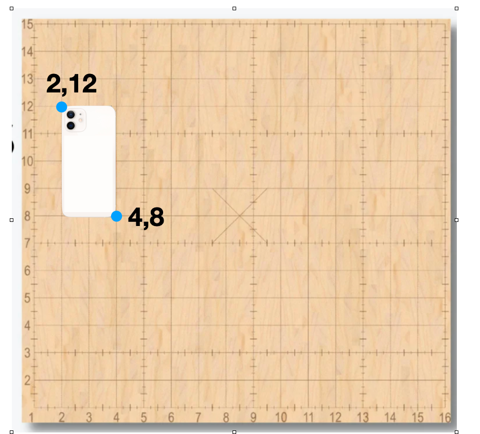
- Place the processed items on the base plate and "read" the coordinates of key points on the base plate. (For example, for a mobile phone, read the coordinates of its upper left corner and lower right corner)

For example, the current key point coordinates of this mobile phone are 2,12 and 4,8
- According to the coordinates of the upper left corner and lower right corner, mark the corresponding positions in the canvas of the host computer software. (For example, place some shapes at corresponding positions as marking points)
- According to the marks of the host computer software, the position and size of the processed object are correctly placed.

- Confirm processing.
Therefore, it can be seen that the absolute coordinate method has the following tedious points:
- You need to read the scale of the coordinates. There are tolerances in the reading process. After the bottom plate is burned by the laser during use, the scale will also be blurred and rendered less legible. Positioning relies on placing your object precisely on the exact coordinates.
Optic machined deep grooves into the base plate to ensure that the scale lines will not be worn by the laser during use.
- Items that don’t align exactly with horizontal and vertical coordinate lines complicate the alignment process. Odd shaped items may obscure lines vital for precise positioning.
It is difficult to directly read the value of the edge point coordinates (red point position) of the iPhone camera in the picture.
- After initial positioning you need to create a mark point in the host computer software based on the read coordinates. Here you need to remember several sets of numbers, and you also need to set up the work. All this does not happen automatically. This process is tedious and can possibly be somewhat inaccurate.

Using digital or mechanical calipers can aid in positioning however, the measured value must be set manually in software versus having the host computer perform the location designation automatically.
Advantages and Disadvantages of Relative Coordinates
Very few coordinate systems result in low errors, but lead to alignment difficulties.
Using the relative coordinate system the user places a positioning spot as the reference point for the engraving or cutting operation. In the example below the reference point is centered on the object to be engraved. X and Y reference lines must be even, and perfectly straight to achieve optimum results. It should be noted that extreme care must be used in measuring the exact center and maintaining perfect straightness of the object to be processed.
The relative coordinate system performs poorly in large-format processing, multi-element processing and repeated processing scenarios.
While processing multiple objects with the relative coordinate system minor positioning differences may introduce alignment errors. Alignment may deteriorate over time or multiple object placements.
Positioning is only as exact as the alignment lines or jig is positioned. While this system may work great on a single object, issues could develop over time with multiple objects being aligned. Human error is easily introduced into this process.
Advantages and Disadvantages of Camera Positioning
The camera positioning is extremely intuitive.
By reconstructing the ideal top view of the object to be processed, the camera can invisibly collect all the dimensional information of the object to be processed.
Therefore, based on the map of the top view, the user can very intuitively observe the size comparison and positional relationship between the processing task and the object to be processed on the host computer software, achieving the effect of previewing the results in advance, which brings extremely excellent intuitiveness.
Objects with variances in height may introduce distortion problems. The camera view only provides a two dimensional view in contrast to the actual three dimensional object placed on the laser engraving surface. Inaccuracies can be introduced. Height differences of the laser head to the object and result in over burning the area or under engraving an area. Curved areas are particularly susceptible to this phenomenon.
In the exaggerated example below, an automobile is depicted in a two dimensional plane. In reality, huge differences in heights are displayed here and the camera can obviously not compensate for three dimensional differences in object height.
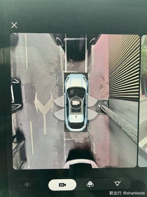
From the 360-degree image of the car, it can be seen that objects with obvious heights will produce obvious distortion; when M1 observes the effect of processing objects on the rotating attachment, it can be seen that the objects have undergone obvious deformation.
This distortion problem is not something that cannot be solved and improved. A simple solution is to place the camera very high away from the observation surface, or to relatively reduce the observation range of the camera to control the degree of distortion, but this method can still only alleviate it. But the distortion cannot be eliminated.
Calibration and mapping issues between camera coordinate system and laser processing coordinate system:
The image of the object to be processed is observed through the camera, and combined with the distance information collected (referring to the height of the camera relative to the surface of the object to be processed), the positional relationship information between the camera and the object to be processed can be determined. However, what we expect to obtain is the relative bottom of the object to be processed. The position information of the bed (further, the laser spot coordinate system that has a relatively stable positional relationship with the bed) needs to be calculated based on additional references.
- For example, a series of feature points with known position information on the base plate can be observed by a camera. The camera observes the relationship between the feature points in the image and the object to be processed, and then estimates the positional relationship between the object to be processed and the feature points, as follows: Because the position of the feature point is known, the position of the object to be processed can be inferred.
- Another method requires that the positional relationship between the camera and the bed be fixed and known. Then based on the known phase position relationship, the camera can also infer the positional relationship of the object to be processed relative to the bed based on the image.
Therefore, in short, compared with other solutions, the camera introduces more coordinate systems. The consistency of the mapping relationship between coordinate systems often introduces the following additional error links:
- Modeling errors caused by incorrect perception of the height relationship between the surface to be detected and the camera
- Distortion caused by different heights of the observed object surface and error corresponding to the distortion
- Error caused by camera installation position; error caused by marker position
Advantages of Pin-point Positioning™ over Known Positioning Methods
Minimum error
Compared with the visual mapping method, that is, the "camera", Pin-point Positioning™ establishes a coordinate system based directly on the processing light spot (at most, it only considers the positional relationship mapping between the positioning light spot and the processing light spot that are also located on the laser head).
Therefore, the errors generated in each link can be reduced. Furthermore, it can even be considered that the error control of this method should be the best among all methods.
More intuitive and automated measurement
Pin-point Positioning™ uses red cross light as a positioning solution, so the measuring red cross light can be clearly projected to any desired position; Pin-point Positioning™ also uses the chip to achieve automated readings and reporting to the software, so the entire The process of measuring and setting reference points/lines in the software can be more automated.
Better usage scenario coverage
Pin-point Positioning™ completes the real-time positioning of the spot coordinates of the guide rail system through the chip. This allows the user to use the relative coordinate method with a lower operating threshold during the positioning process, but at the same time what is presented in the host computer software is Absolute coordinate system canvas.
This effectively solves the shortcomings of the relative coordinate method in covering multiple processing items and repeated processing task scenes.
In addition, as mentioned in the previous point, Pin-point Positioning™ has fewer (or even no) restrictions on the measurement of key point coordinates of processed items, and there is no need to solve the visual mapping method's problems with items with serious height differences (such as items in rotating processing scenarios).
High-low difference distortion problem. Therefore, overall, Pin-point Positioning™ has obvious scene coverage advantages compared to other solutions.
For more questions. Please join our Facebook group to get inspired!

Related Posts

Introducing xTool M2: The Smart and Easiest Color Craft Laser

On the Road with xTool MakerFest Tour